2025-09-25
This article illustrates how I am setting up an Arduino project.
Rules obeyed:
- No file larger then one A4 page (well … )
- My own subroutines in separate files in a common directory.
Make them accessible via soft links. - The Arduino libraries in a common directory.
Make them accessible via soft links.
1. Create directories for all used ingredients
|
1 2 3 4 |
$ mkdir –p ~/programming $ mkdir –p ~/programming/arduino_libraries $ mkdir –p ~/programming/my_common_files $ mkdir –p ~/programming/arduino_pico_debug_test |
2. Create the soft link pointing to the Arduino libraries.
|
1 2 |
$ cd ~/programming/arduino_pico_debug_test $ ln –s ../arduino_libraries/libraries libraries |
3. Open the blink example and save it in the chosen directory.
tree should return:
|
1 2 3 4 5 6 7 8 9 10 11 12 13 14 15 16 17 18 19 20 |
$ tree ./programming/arduino_pico_debug_test/ ./programming/arduino_pico_debug_test/ ├── blink_debug_test │ ├── blink_debug_test.ino └── libraries -> ../arduino_libraries/libraries ./programming/arduino_libraries/ └── libraries ├── Adafruit_BusIO │ ├── Adafruit_BusIO_Register.cpp │ ├── Adafruit_BusIO_Register.h ... ├── MCP23S17 │ ├── Examples │ │ ├── mcp23s17_bit_example │ │ │ └── mcp23s17_bit_example.pde ... ├── TFT_eSPI │ ├── CMakeLists.txt │ ├── docs ... |
4. Now it is time to do the first test.
Check if you are able to upload the program.
- Choose the board you are using. In my case: Raspberry Pi Pico W
- Check if the USB device is available with lsusb.
It should return:
Device 006: ID 2e8a:000c Raspberry Pi Debug Probe (CMSIS-DAP) - From the menu select:
Tools -> Upload Method -> PicoProbe/Debugprobe (CMSIS-DAP) - Load the program with CTRL+U
- If everything is OK you should see the LED blinking
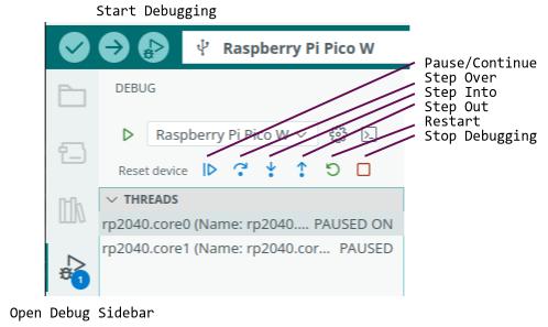
5. Let’s do the first debug test by single stepping the program.
- Click the „Start Debugging“ button left from the board selector drop down field.
The „gdb-server“ window should not show any error , but something like:
halted due to debug-request, current mode: Thread - The „Debug Console“ should display somthing similar.
By the way instead of clicking the buttons with the mouse there keyboard shortcuts available.
$$
\begin{array}
{ c | c }
Funktion & Tasten\\
\hline
Pause/Continue & F5 \\
Stop Debugging & Shift+F5 \\
Step Over & F10 \\
Step In & F11 \\
Step Out & Shift+F11 \\
Restart & Ctrl+Shift+F5 \\
\end{array}
$$
5. The program is still running.
6. Mark a breakpoint with a click left from the row numbers.
Make sure you are using an actual compiled version.
If some modifications have been applied the synchronization between code and rows has changed the breakpoint may not be on the wanted position anymore.
For uploading a new version you have to stop the debugging process.
Otherwise you may get:
Error: CMSIS-DAP command CMD_INFO failed.
Failed uploading: uploading error: exit status 1
7. Refresh the program
- Stop Debugging
- Upload program
- Start Debugging
- Place your first breakpoint
- Click Reset
Now you should have a situation like the following.
I placed a breakpoint on the pinmode() function and after a reset the debugger stops there with indicating the whole row.

If you now click „Step Over“ you may assume it is calling the pinmode function and continues in the endless loop, you are wrong.
It opens the hidden main.cpp and steps through this file.
This implies we should also place a breakpoint on the first digital write() within the loop and run to this one with the continue button.
- Click Reset
- Place the second Breakpoint
- Click Continue
But once again after the last „Step Over“ the last delay() it enters the main.cpp again.
This maybe interesting but not in the moment.
To avoid this we do need a dummy instruction.
In older projects using PICs with MPLABX from Microchip I used a NOP() as a dummy function to place a Breakpoint.
Let’s do something similar here, too.
I will use a macro:
#define NOP() asm(“nop”)
|
1 2 3 4 5 6 7 8 9 10 11 12 13 14 15 16 17 18 19 20 |
#define NOP() asm(“nop”) // the setup function runs once when you press reset or power the board void setup() { // initialize digital pin LED_BUILTIN as an output. pinMode(LED_BUILTIN, OUTPUT); } // the loop function runs over and over again forever void loop() { digitalWrite(LED_BUILTIN, HIGH); // turn the LED on (HIGH is the voltage level) delay(1000); // wait for a second digitalWrite(LED_BUILTIN, LOW); // turn the LED off by making the voltage LOW delay(1000); // wait for a second NOP(); } |
Now the process looks like this:
- Click Stop Debugging button, the square
- Change the program and add the define and the NOP()
- Upload the program
- Continue to the second breakpoint
- Step Over repeatedly and when the NOP() is highlighted
- Click Continue to get back to the second breakpoint
Now by executing this we are able to see the LED becoming ON or OFF on purpose.
The delays are not necessary anymore when this program is supposed to be something productive.
Before continueing I will modify the program so it is not using the blocking delay anymore.
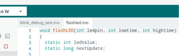
I do have a common function for flashing any digital IO.
|
1 2 3 4 5 6 7 8 9 10 11 12 13 14 15 16 17 18 19 20 21 |
void flashLED(int ledpin, int lowtime, int hightime) { static int ledValue; static long nextUpdate; if (millis() > nextUpdate) { ledValue = !ledValue; if(ledValue) { nextUpdate = millis() + lowtime; } else { nextUpdate = millis() + hightime; } digitalWrite(ledpin, ledValue); } } /* end flashLED */ |
I will make this file accessible to the blink_debug_test by linking to this file.
|
1 |
ln –s ../../kps_common/flashled.ino flashled.ino |
This should show up now as a tab within the Arduino IDE.
If necessary, modifications may be applied, too.
In addition some definition are necessary for low- and hightime.
This function assumes the LEDs are connected to ground lighting them with HIGH.
There are some addon boards with connecting the LEDs to +3V3.
In this case low- and hightime maybe used in a reversed manner.
The Pico W is using the LED via the CYxxxx device and needs reversed values.
Now the program looks like this:
|
1 2 3 4 5 6 7 8 9 10 11 12 13 14 15 16 17 18 19 20 21 22 23 24 25 26 |
#define NOP() asm(“nop”) /******************************************************************************/ // Pico W #define LED_HIGH_TIME 500 #define LED_LOW_TIME 20 /******************************************************************************/ // the setup function runs once when you press reset or power the board void setup() { // initialize digital pin LED_BUILTIN as an output. pinMode(LED_BUILTIN, OUTPUT); } // the loop function runs over and over again forever void loop() { NOP(); flashLED( LED_BUILTIN // int ledpin ,LED_LOW_TIME // int lowtime ,LED_HIGH_TIME // int hightime ); } |
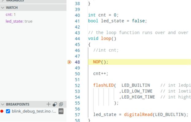
Place a Break point on the NOP() and use „Continue“ to step the program.
The OFF time is long therefore single stepping is not really useful.
I want to show how to observe the content of a variable.
A variable cnt should count how often we reach the NOP().
For showing the variable cnt under Watch it must be declared global, otherwise local is not detected.
I have to investigate howto add local varaiables to the watch.
Stay tuned.

When clicking the “+” to add a watch it says “Edit Expression”.
Sounds promising.
Test to see the LED_BUILTIN status.
Using digitalRead(LED_BUILTIN) doesn’t work, because I am using the Pico W.
Here we have to read the value into a global variable.
This article described some basic things when starting an Arduino project.
The need to learn more led into a separate Article about odds and traps with the debugger.
Warum Einfaches die Dinge verkompliziert <br>oder <br>„Debugging für Anfänger“.
I wrote it in german, but it may still be useful. 😉